Spirit Week 2018
June 2, 2018
IntelliScreen @ UPMC
October 6, 2018
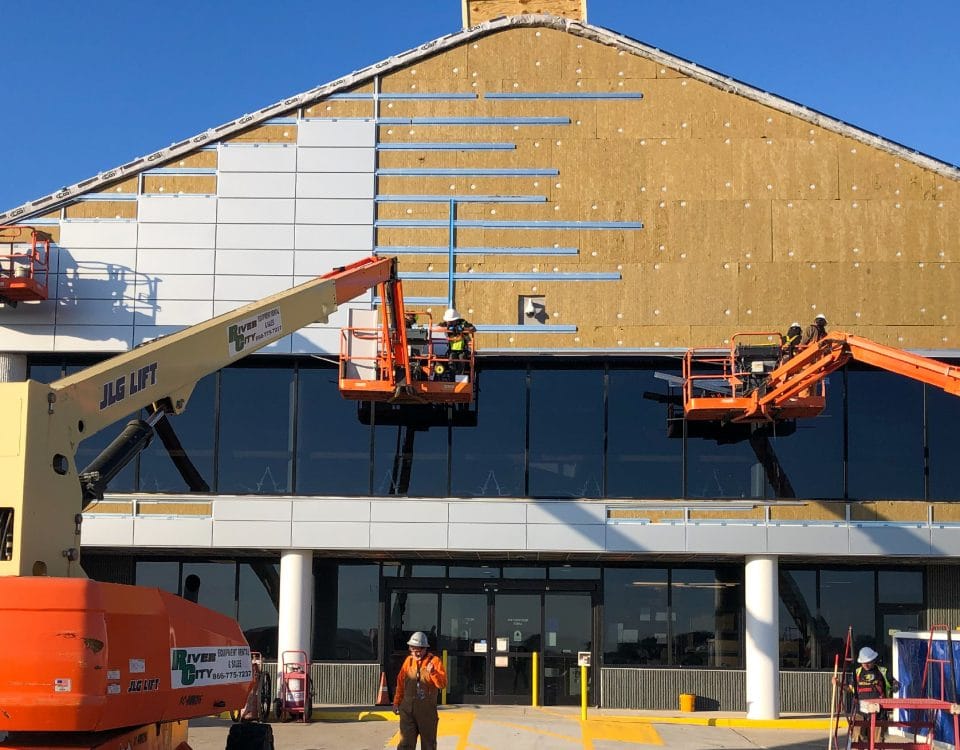
Horizontal Hat Channel Attachment Through High Density Mineral Wool Continuous Exterior Board Insulation

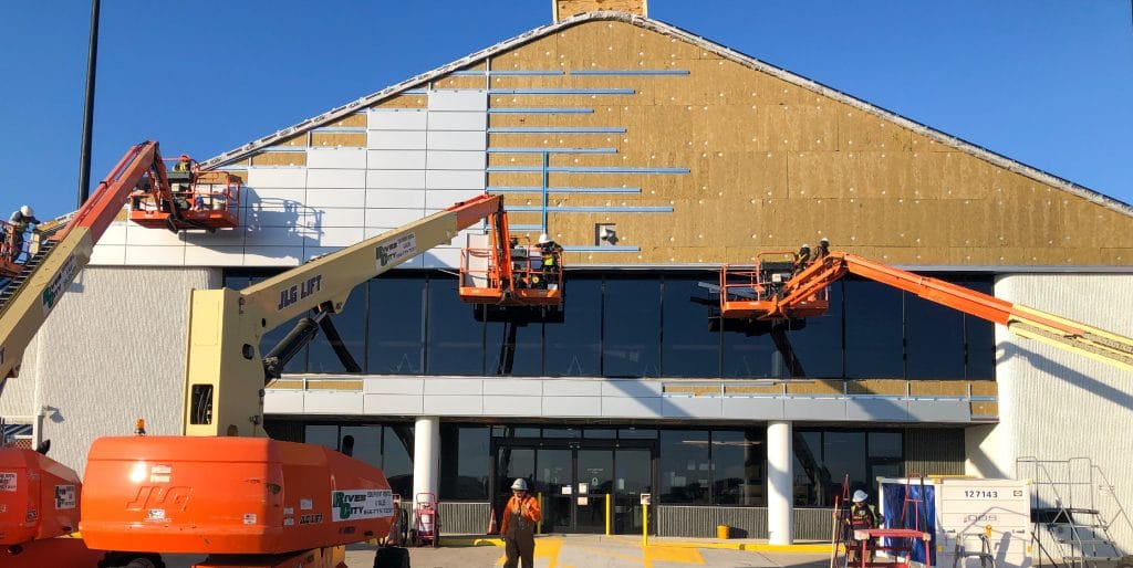
The intent of this Technical Bulletin is to validate the specific structural connection utilized to attach IMETCO’s vented rainscreen horizontal hat channel metal framing through high density mineral wool continuous exterior board insulation and wall sheathing into a metal stud backup wall system. IMETCO employs this specific connection method with the IntelliScreen™ complete rainscreen assembly and other vertical wall assemblies.

Consider a critical scenario of a maximum weight metal panel, maximum thickness insulation board, and minimum gauge stud wall at maximum spacing (ref. Fig. A).

20ga steel studs @ 24” o.c. spacing

1/2” gypsum exterior sheathing board

3.9” Thick CIS Insulation Board

Density 11.0 PCF
R-Value 3.9 per inch @ 75°F
Compressive Strength = 8.5 psi

18ga galvanized steel vented hat channel

Oriented horizontally, and installed at 24” o.c. (vertical) to match wall panel dimension
Bottom Flange Width =1.5”
Pitch between pre-punched screw holes in opposing bottom flanges =5”

1/4”-14 screws attaching hat channels to steel stud wall

Minor diameter = 0.0192 in.; area of minor diameter = 0.0269 in2
Modulus of Elasticity = 29 x 106 psi
Tensile strength = 4,275 lbs.
Ultimate Average Pullout in 20 gauge steel = 343 lbs. per screw

1.5mm zinc wall panel
24” vertical panel dimension

Unit weight of 1.5mm zinc sheet = 2.21 psf
Assume 30” zinc strip width to produce 24 in. panel coverage width
Dead Load of Metal Cladding = 2.21 x 30/24 = 2.75 psf; conservatively consider 4.0 psf max cladding load.

Assembly Thermal Value:

3.9 in. Insulation = 3.9 in. x R-3.9 per in. = R-15.21
1/2 in. Sheathing Board = R-0.45
Inside Air Film = R-0.68
Outside Air Film = R-0.17
Assembly U-Value = 1/(15.21 + 0.45 + 0.68 + 0.17) = 0.061
Assembly U-Value complies with Opaque Wall U value requirements of the 2012 International Energy Conservation Code
for North American climate zones 1–7.

Axial Load on Screws

Tributary area of metal cladding on each screw couple = 2’ x 2’ = 4 square feet
Metal cladding panel dead load = 4.0 psf
Dead load applied to each screw couple, W = 4.0 psf x 4 square feet = 16 lbs per screw couple

Check Tensile Stress in Screw
Check Pullout in 20ga Stud
Check Bearing/Compressive Stress in Insulation Board
  • Bearing area of one hat channel flange is 1.5 in. x 24 in.
  • Conservatively consider that maximum compressive stress in the insulation board occurs in only a 1.5 in. x 4 in. area immediately surrounding the fastener.
Determine Maximum Deflection in Exterior Cladding

Maximum Strain (Elongation) of Screw in Tension:

Downward Deflection (Sag) in Exterior Cladding Panel:

Correlation to Physical Laboratory Test Results

The preceding calculation follows established and accepted structural engineering methodology, and is a conservative analysis in many respects. Physical testing has been conducted on a similar arrangement of furring straps attached through mineral wool exterior continuous board insulation.

In those tests (ref. the attached Building Science Corporation of Waterloo, Ontario report dated August 16, 2011), an insulation board with a density of only 8.0 pcf and compressive strength of only 5.5 psi was tested repetitively with loads simulating up to a 30 psf cladding system. At a similar cladding load of 3 psf, the physical testing resulted in deflection measurements of about 0.002” on the initial loading cycle, and less than 0.001” on subsequent loading cycles.

The physical laboratory testing results indicate an experimental deflection of about 1/10th the magnitude of the preceding calculation, further supporting the position of the calculation being a conservative, worst-case scenario.

Prepared By:

Q. Jonnie Hasan, PE, BECxP, CxA+BE
Director of Engineering & Sales Support

Thinking about your next project?

LET'S GET STARTED

Resources

Search
Generic filters
Exact matches only